tyger23
Active member
- Joined
- May 15, 2022
- Messages
- 91
- Reaction score
- 110
- Points
- 33
So, now my thoughts...
ASSUMING that we are using readily available aftermarket style harness systems (and not some Kia official harness that's not currently available):
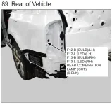
1. The standard turn signals are the biggest and most basic issue here. They seem to route directly from the central computer/fuse/junction box under the driver's side dashboard straight to the turn signals with no junction connectors between them. They are only readily available at "F12" and "F13", which are the connectors to the actual tail lamps themselves.
2. All of these wires should be available in the bundle that's in the left side rear wheel well, but they're going to be bundled together and not easy to determine or separate or get to.
3. There's a connector called "F11", which seems to house several of the necessary signals, but be forewarned that it's supposedly located in the ceiling of the rear cargo area. This isn't where I would focus my time, but I highlight it as an option for many of the signals.
So, what would I plan to do? (PLEASE NOTE - IF YOU DO THIS, YOU DO IT AT YOUR OWN RISK!!!! I TAKE NO RESPONSIBLITY FOR WHAT YOU CHOOSE TO DO TO YOUR OWN CAR. DO YOUR OWN RESEARCH AND MAKE YOUR OWN DECISIONS.)
I'll post more connector pinouts in a second...
ASSUMING that we are using readily available aftermarket style harness systems (and not some Kia official harness that's not currently available):
1. The standard turn signals are the biggest and most basic issue here. They seem to route directly from the central computer/fuse/junction box under the driver's side dashboard straight to the turn signals with no junction connectors between them. They are only readily available at "F12" and "F13", which are the connectors to the actual tail lamps themselves.
2. All of these wires should be available in the bundle that's in the left side rear wheel well, but they're going to be bundled together and not easy to determine or separate or get to.
3. There's a connector called "F11", which seems to house several of the necessary signals, but be forewarned that it's supposedly located in the ceiling of the rear cargo area. This isn't where I would focus my time, but I highlight it as an option for many of the signals.
So, what would I plan to do? (PLEASE NOTE - IF YOU DO THIS, YOU DO IT AT YOUR OWN RISK!!!! I TAKE NO RESPONSIBLITY FOR WHAT YOU CHOOSE TO DO TO YOUR OWN CAR. DO YOUR OWN RESEARCH AND MAKE YOUR OWN DECISIONS.)
- I would probably obtain any of the trailer wiring harnesses for the 2022 telluride, cut off the vehicle side mating connector, and splice in the wires as necessary to the 2023. It seems clear to me that no matter what, you'll need to use some type of "MODULITE" converter to separate the trailer wiring from the vehicle wiring to prevent the vehicle wiring from being overloaded.
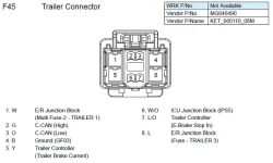
- I would obtain the "STOP LAMP" signal from F45, pin 6. F45 is the white "trailer connector" found inside the jack well. PLEASE NOTE: I have seen some discrepancy on this signal inside the schematics/connector pinouts, so test this out before using. Also - note that the STOP lamp may not be necessary as the 2023 telluride seems to use a "2-wire" type system where the stop lamps and turn signals are integrated.
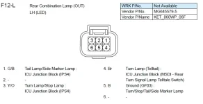
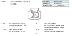
- I would obtain the "TAIL LAMP" signal from F12 or F13, pin 1. F12 is the connector for the left hand tail-light, and F13 is the connector for the Right-hand tail light.
- I would obtain the "LEFT TURN" signal from F12, pin 3.
- I would obtain the "RIGHT TURN" signal from F13, pin 3.
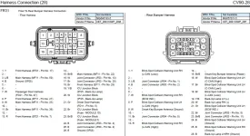
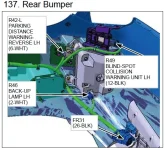
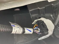
- I would obtain the "BACKUP" signal from FR31, pins 19 or 20. FR31 is the connector located under the car in the same location as the old trailer connector from 2022. This is the connector that I pictured in my very first post on this thread.
- I would power the "MODULITE" type controller using the power obtained from F45, pin 1.
- Any other signals for the 7-way connector (AKA for trailer brake controllers) should be readily available at F45. Wire them at your own discretion.
I'll post more connector pinouts in a second...
Last edited:


