-
Hint: Use a descriptive title for your new message
If you're looking for help and want to draw people in who can assist you, use a descriptive subject title when posting your message. In other words, "I need help with my SUV" could be about anything and can easily be overlooked by people who can help. However, "I need help with my transmission" will draw interest from people who can help with a transmission specific issue. Be as descriptive as you can. Please also post in the appropriate forum. The "Lounge" is for introducing yourself. If you need help with your leather interior, please post in the Interior section - and so on... This message can be closed by clicking the X in the top right corner. -

You are using an out of date browser. It may not display this or other websites correctly.
You should upgrade or use an alternative browser.
You should upgrade or use an alternative browser.
Installed Proximity Door Lock/Unlock Module
- Thread author Lith_SXPN
- Start date
Kevyn
New member
- Joined
- Mar 28, 2021
- Messages
- 16
- Reaction score
- 13
- Points
- 3
Trying to install the ISG module. Pin 3 on F52 is NOT 12v acc, pin 1 is, it's a red wire. Pin 24 on F51 is GND, black wire. Not sure about the others, don't want to continue and fry something. @Lith_SXPN is this pinout for the Telluride or some other vehicle?If anyone is looking to install the ISG/Auto Hold module, here are the pin outs. The module is untested(by me) and pin out does not guarantee the module will work.
Location of the connectors. You need F51, and F52
View attachment 13633
F51 Connector
Pin 4 - Auto Hold
Pin 8 - ISG Switch Signal
Pin 10 - ISG Switch Indicator (Not used for resistor mod or EZLED Module)
Pin 24 - Ground
View attachment 13634
F52 Connector
Pin 3 - 12v Acc
View attachment 13635
GreekWiz
Well-known member
Too late to get in on this?
Yes, ordered, arrived from Korea and some in the USA already getting theirs.
If you search through this topic after the order was made there is 1-2 others that missed out, that you could start with them.
GreekWiz
Well-known member
I saw this posted on Facebook, and immediately thought of this thread, because most people I asked to join on the group buy thought it was a waste of money.... LOL

______________________________
Lith_SXPN
Well-known member
Those pinouts are from Telluride service manual. Often times, the pin numbers are marked looking from the front of the plug(opposite wire side). Can you take a picture of the plug?Trying to install the ISG module. Pin 3 on F52 is NOT 12v acc, pin 1 is, it's a red wire. Pin 24 on F51 is GND, black wire. Not sure about the others, don't want to continue and fry something. @Lith_SXPN is this pinout for the Telluride or some other vehicle?


looks like you have the right pins. Worst case, you may have to use a multimeter to measure the voltage on pin 3.
Last edited:
Kevyn
New member
- Joined
- Mar 28, 2021
- Messages
- 16
- Reaction score
- 13
- Points
- 3
That was my first thought, except pin 4 on F51, looking from the back, would be empty. I'll take a picture in the morning.Those pinouts are from Telluride service manual. Often times, the pin numbers are marked looking from the front of the plug(opposite wire side). Can you take a picture of the plug?
Lith_SXPN
Well-known member
Edited my post above to include the SM pinouts.That was my first thought, except pin 4 on F51, looking from the back, would be empty. I'll take a picture in the morning.
______________________________
Kevyn
New member
- Joined
- Mar 28, 2021
- Messages
- 16
- Reaction score
- 13
- Points
- 3
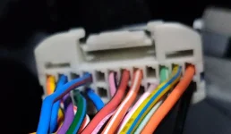
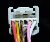
Okay, images of F51 & F52 attached.Edited my post above to include the SM pinouts.
Looking from the back the pins are labeled from left to right.
The drawings that are above are viewed from the front of the connector.
Connector F52 pin 1 (red) - 12v continuous
pin 3 (brown/black) - 12v switched
I just need to see if the module needs switched 12v and will remember last setting or I'll have to use continuous 12v.
Attachments
Lith_SXPN
Well-known member
It doesn't require constant(continuous) 12v. Acc(switched) is all you need if I recall from my Stinger ISG installation(same module).Okay, images of F51 & F52 attached.
Looking from the back the pins are labeled from left to right.
The drawings that are above are viewed from the front of the connector.
Connector F52 pin 1 (red) - 12v continuous
pin 3 (brown/black) - 12v switched
I just need to see if the module needs switched 12v and will remember last setting or I'll have to use continuous 12v.
Lith_SXPN
Well-known member
I think @rwhite4573 printed out the same instruction as the first post of this thread. Just compare your printed version with 1st post. If it's not the same, go with 1st post.Hello Telly friends just got home from vacation & my module came...should I just follow the instructions sheet that came with it??
______________________________
Lith_SXPN
Well-known member
Dip switch settings for ISG Module installation only:

Switch 1 Auto Hold // Off: Memory Mode - On: Manual Mode
Switch 2 ISG // Off: Memory Mode - On: Manual Mode
It is recommended to use the Manual Mode per seller page, but memory mode works fine with my Stinger.
Memory Mode - Restores(remembers) your last setting.
Manual Mode - Force emulates 1x button press at every start up. Recommended if you don't like the memory mode or have problems with alarm/remote start.
It takes up to 3 seconds to save/restore your setting.
Kevyn
New member
- Joined
- Mar 28, 2021
- Messages
- 16
- Reaction score
- 13
- Points
- 3
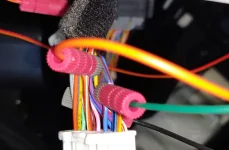
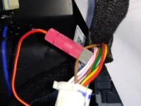
Okay, connected everything up as follows:It doesn't require constant(continuous) 12v. Acc(switched) is all you need if I recall from my Stinger ISG installation(same module).
ISG Module Wire Harness
red/yellow 12v --- F52 pin 3 - brown/black - 12v switched
black - gnd --- F51 pin 24 - black/green - gnd
green - auto hold --- F51 pin 4 - blue/red - auto hold switch -----> NOTE: this is L/O in the above pinout diagram
orange - isg --- F51 pin 8 - orange/white - isg switch
1. The ISG module was disconnected from it's wire harness to check for continuity to the posi-tap connectors. Everything checked fine.
2. Plugged in the ISG module and started the vehicle. ISG switch stayed yellow(disabled), would not toggle.
3. Auto Hold would toggle according to the dash.
4. Did not see any lights on the ISG module, yet there are leds on the board.
5. Checked 12v(red/yellow) to ground(black) at ISG module showed 1.6v - disconnected module - still showed 1.6v (had 12v before install)
6. Removed ISG module and connected to another 12v source and still no leds (Should the leds be lit when powered?).
Unfortunately my ISG module doesn't work. The Telluride still works correctly when pressing the ISG switch to enable/disable (with module removed).
@Lith_SXPN any idea which fuse(if any) F52 pin 3 goes too? I see that the diagram shows ILL.(+) for pin 3, yet the illumination for the buttons work correctly.
Attachments
Kevyn
New member
- Joined
- Mar 28, 2021
- Messages
- 16
- Reaction score
- 13
- Points
- 3
For ISG/Auto Hold Module install
Everything is working correctly as connected as follows:
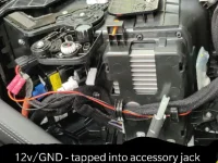
ISG Module Accessory Jack
red/yellow 12v --- red wire - 12v switched
black - gnd --- black wire - gnd
ISG Module Wire Harness
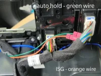
green - auto hold --- F51 pin 4 - blue/red - auto hold switch -----> NOTE: this is L/O in the above pinout diagram
orange - isg --- F51 pin 8 - orange/white - isg switch
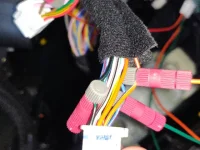
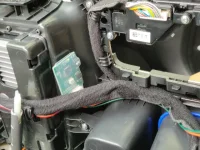
I attached the ISG/AutoHold module on the wall to the wireless charging pad with double faced tape.
I went with the accessory jack for power because F52 was not providing enough current(module wouldn't power on).
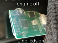
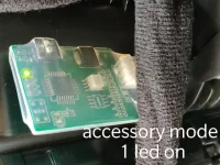
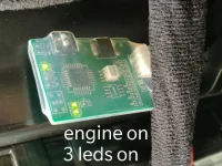
The pictures below show which state the leds will be in depending on engine on/off or accessory mode.
note: when switching to accessory mode all three leds will light and then the bottom two in the picture will turn off.
Everything is working correctly as connected as follows:
ISG Module Accessory Jack
red/yellow 12v --- red wire - 12v switched
black - gnd --- black wire - gnd
ISG Module Wire Harness
green - auto hold --- F51 pin 4 - blue/red - auto hold switch -----> NOTE: this is L/O in the above pinout diagram
orange - isg --- F51 pin 8 - orange/white - isg switch
I attached the ISG/AutoHold module on the wall to the wireless charging pad with double faced tape.
I went with the accessory jack for power because F52 was not providing enough current(module wouldn't power on).
The pictures below show which state the leds will be in depending on engine on/off or accessory mode.
note: when switching to accessory mode all three leds will light and then the bottom two in the picture will turn off.
______________________________
Attachments
Last edited:
adeokesola
Member
- Joined
- Dec 28, 2020
- Messages
- 44
- Reaction score
- 13
- Points
- 8
At the risk of sounding dumb, The more I read all these installs the more confused I am getting. Someone Pls do a video. 
justinconroy
New member
- Joined
- Mar 1, 2021
- Messages
- 23
- Reaction score
- 8
- Points
- 3
If you're installing the proximity door lock/unlock it's easy if you just follow the instructions from Lith_SXPN. He put together the PDF you can find at the link below.At the risk of sounding dumb, The more I read all these installs the more confused I am getting. Someone Pls do a video.
Installed Proximity Door Lock/Unlock Module
rwhite4573
Active member
- Joined
- Jul 4, 2019
- Messages
- 305
- Reaction score
- 205
- Points
- 43
I also sent a color copy of the door proximity instructions attached above with the door proximity modules I shipped.If you're installing the proximity door lock/unlock it's easy if you just follow the instructions from Lith_SXPN. He put together the PDF you can find at the link below.
Installed Proximity Door Lock/Unlock Module
Lith_SXPN
Well-known member
Glad to hear everything worked out!For ISG/Auto Hold Module install
Everything is working correctly as connected as follows:
ISG Module Accessory Jack
red/yellow 12v --- red wire - 12v switched
black - gnd --- black wire - gnd
ISG Module Wire Harness
green - auto hold --- F51 pin 4 - blue/red - auto hold switch -----> NOTE: this is L/O in the above pinout diagram
orange - isg --- F51 pin 8 - orange/white - isg switch
I attached the ISG/AutoHold module on the wall to the wireless charging pad with double faced tape.
I went with the accessory jack for power because F52 was not providing enough current(module wouldn't power on).
The pictures below show which state the leds will be in depending on engine on/off or accessory mode.
note: when switching to accessory mode all three leds will light and then the bottom two in the picture will turn off.